Run the Neato Simulator
Purpose of this How-to
This document will help you run the Neato simulator. Before going through these instructions, make sure that you have already
What is a Robot Simulator?
Without getting into too much detail, a robot simulator that simulates a robot interacting with some sort of environment. As such, a simulator will typically provide the following major functionality.
- It will provide a means to specify the physical layout of the robot’s environment (e.g., the location of obstacles, the physical properties of various surfaces).
- It will provide a means to specify a robot model (e.g., the robot’s sensors, actuators, mass, inertia, etc.).
- It will provide simulated sensor data (i.e., what would the robot’s sensors have reported if the robot were in a particular environment in a particular location).
- It will provide a means to execute simulated motor commands (i.e., it will let you tell the robot to move).
- It will provide a way to visualize the simulation state (e.g., as a graphical rendering).
One nice thing about ROS is that the usage of a publish and subscribe structure provides a very clean separation between the robot itself and code that you will write to program the robot. For instance, you can write a motor control node that sends commands to the topic cmd_vel. This program can work with any real or simulated robot so long as it subscribes to the cmd_vel topic and executes the appropriate motor command in response to the messages it receives (e.g., the motor command might involve moving a real motor or it might involve moving a simulated robot).
Differences with RViz
Oftentimes students will be confused as to what the difference is between RViz and a robot simulator. RViz allows you to visualize a robot’s sensor data. As such, RViz has a graphical interface that can look a lot like the graphical interface of the robot simulator. In contrast, RViz does not have any means to execute a simulated motor command or generate simulated sensor data: it can only display the data that it receives.
The Neato Simulator
We will be using the popular Gazebo software for robot simulation. Gazebo is a very powerful and customizable simulator that will be especially useful in this online (virtual) version of the course.
Starting the Simulator
- Start roscore
Got to a terminal and run the following command.
$ roscoreYou should see output that look like the following.
... logging to /home/pruvolo/.ros/log/5e5e9c82-e17e-11ea-bd40-4997ac5b185e/roslaunch-ubuntu-114522.log Checking log directory for disk usage. This may take a while. Press Ctrl-C to interrupt Done checking log file disk usage. Usage is <1GB. started roslaunch server http://ubuntu:40119/ ros_comm version 1.15.8 SUMMARY ======== PARAMETERS * /rosdistro: noetic * /rosversion: 1.15.8 NODES auto-starting new master process[master]: started with pid [114559] ROS_MASTER_URI=http://ubuntu:11311/ setting /run_id to 5e5e9c82-e17e-11ea-bd40-4997ac5b185e process[rosout-1]: started with pid [114576] started core service [/rosout] - Launch Gazebo
You can launch your robot in many different simulated worlds. For instance, to launch your robot in a simulated obstacle course, in a new terminal, run the following command.
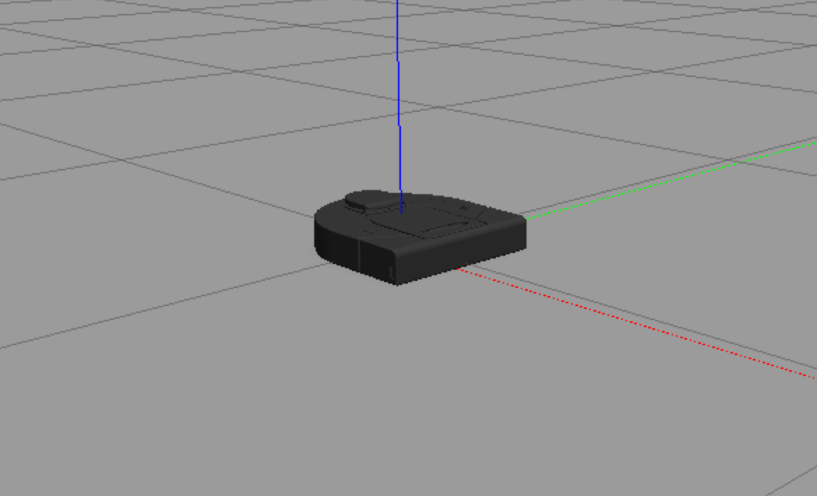
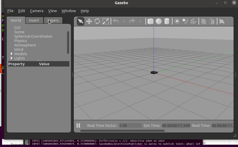
$ roslaunch neato_gazebo neato_gauntlet_world.launchIf all went well, you will see a bunch of output stream by and a visualization that looks like the following.
Instead if you want to run your Neato around the Olin dining hall, try the following command.
$ roslaunch neato_gazebo neato_dh.launchIf you want to create your own world, you can put the Neato in an empty world and then follow our instructions for populating your own world.
$ roslaunch neato_gazebo neato_empty_world.launchOptional: Loading the camera module. If you want to load a simulated video camera on your Neato, you can modify the instructions in the previous step.
$ roslaunch neato_gazebo neato_dh.launch load_camera:=trueThis will result in a white box appearing over your Neato (the simulated camera). You can look at the images using, e.g., rqt_gui
Using the Gazebo Graphical Interface
The Gazebo website has a guide on using Gazebo’s graphical interface.
Available Topics
This documentation gives the high-level purpose of each topic. To explore more, you can use the following command to get more information.
$ rostopic info topic-name
If you want to know more about a message you see in the output of rostopic you can use the following command (note that the -r flag can be ommitted if you want to the mesasges nested within the top-level message to be expanded).
$ rosmsg show msg_package_name/MessageName -r
accel
This is the linear acceleration of the Neato in meters per second squared along each axis of the Neato. This same information is included in the imu topic (although there it is nested further).
bump
This topic contains four binary outputs corresponding to each of the Neato’s four bump sensors. In the simulator, all bump sensors are either on or off (no differentiation is made between the bump sensors).
bumper
This is an internal topic to Gazebo. If you are curiouts, you can look at the output as you run into something, but you don’t need to worry about it in this class.
clock
This is the simulator clock. This is useful for executing commands based on elapsed time. It is preferable to use this clock rather than the wall clock (your computer’s system clock) since the simulation might not run at the same rate as realtime. You don’t typically want to subscribe to this topic directly. Instead, you can access the time through rospy (see the ROS tutorials page for details).
cmd_vel
You publish to this topic to set the robot’s velocity. The linear.x direction sets forward velocity and angular.z sets the angular velocity.
encoders
These tell you the linear travel of each wheel (left is the first element of the array and right is the second) since the simulation started. You do not have to subscribe to this directly, but instead you can use the odom topic or the tf module if you are you are just interested in knowing an estimate of where the robot is relative to where it started.
gazebo/link_states
This is a Gazebo specific topic (see the Gazebo docs on ROS communication).
gazebo/model_states
This is a Gazebo specific topic (see the Gazebo docs on ROS communication).
gazebo/parameter_descriptions
This is a Gazebo specific topic (see the Gazebo docs on ROS communication).
gazebo/parameter_updates
This is a Gazebo specific topic (see the Gazebo docs on ROS communication).
gazebo/set_link_state
This is a Gazebo specific topic (see the Gazebo docs on ROS communication).
gazebo/set_model_state
This is a Gazebo specific topic (see the Gazebo docs on ROS communication).
imu
This is the simulated IMU (intertial measurement unit). It has linear acceleration and angular velocity.
joint_states
These tell you the total rotation (in radians) of each wheel. Note that this is a “ground truth” value, meaning that it is not estimated from sensors but instead comes from Gazebo. In a scenario with a real robot, you wouldn’t have access to this.
odom
This tells you the robot’s position relative to its starting location as estimated by wheel encoders. You can get this inforation more flexibly through the ROS tf module, but this is a relatively easy way to get started.
projected_stable_scan
This provides the LIDAR measusrements (think of these as detected obstsacles or objects from the environment). In contrast to the scan topics, these measurements are in the odometry frame (rather than relative to the robot) and are in Caretesian rather than polar coordinates. There is no need to use this topic, but for some applications it is nice to have.
raw_vel
you publish to this topic set the left and right wheel velocities independently (rather than setting linear and angular velocities). You can use this is cmd_vel for controlling the robot, whichever is easier.
rosout
This is a topic provided by ROS. See the ROS docs on rosoutfor more information.
rosout_agg
This is a topic provided by ROS. See the ROS docs on rosoutfor more information.
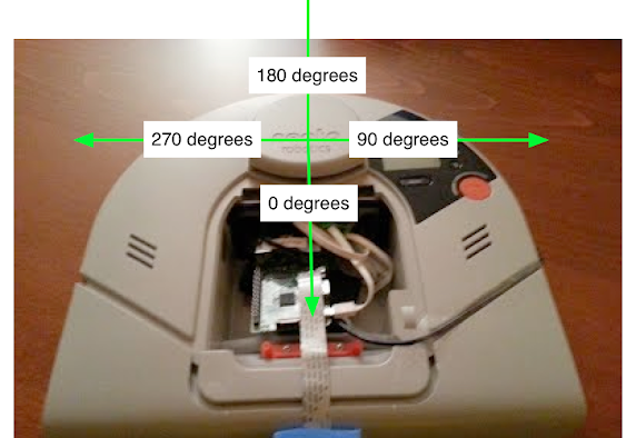
scan
These are the measurements of the Neato’s LIDAR. This diagram should help you with the project. It shows the angles for the laser range data coming from the Neato and how it maps onto the Neato’s physical layout.
The LaserScan message consists of a number of attributes:
$ rosmsg show sensor_msgs/LaserScan
std_msgs/Header header
  uint32 seq
  time stamp
  string frame_id
float32 angle_min
float32 angle_max
float32 angle_increment
float32 time_increment
float32 scan_time
float32 range_min
float32 range_max
float32[] ranges
float32[] intensities
Most of these attributes you can ignore for the purposes of this assignment. The one that you will really need to dig into is ranges. The ranges attribute provides 361 numbers where each number corresponds to the distance to the closest obstacle as detected by the laser scan at various angles relative to the robot. Each measurement is spaced exactly 1 degree apart. The first measurement corresponds to 0 degrees in the image of the Neato above. As the degrees in the image go up, so to does the index in the ranges array. Where does 361 come from? The last measurement (index 360) is the same as the first (index 0). Why do we do this craziness?!? We have to do this to adhere to some ROS conventions around LaserScan data that will be important later in the class. For now, you can safely ignore the last measurement (index 360).
stable_scan
This gives the same data as scan except the timestamp is automatically adjusted to keep the detected points stable in the odometry frame. This topic is really only need with the physical Neato robot where the precise timing of the LIDAR is not available due to hardware limitations.
tf
This is provided by the ROS tf2 module to update the relationhsip between various coordinate systems. Typically you don’t subscribe to it directly but instead use the Python tf module.
tf_static
This is provided by the ROS tf2 module to update the relationhsip between various coordinate systems. Typically you don’t subscribe to it directly but instead use the Python tf module.
Using Rviz with the Simulator
Once the simulator is running, to start rviz, run the following command.
$ rosrun rviz rviz
Once you get to rviz, the warmup project has some good instructionns for how to see the robot and its LIDAR.
- Set the base_frame to
odom - Add a visualization of the Neato’s stabilized laser scan (topic
scan). This is most easily found by using the “By topic” tab. Make sure to adjust the size of the markers so you can see them easily). - Add a visualization of the Neato itself (this can be done by selecting “Robot Model” from the insert menu”)
- Add a visualization of the Neato’s camera feed (topic
camera/image_raw) (this only applies if you launched the simulation withload_camera:=true)
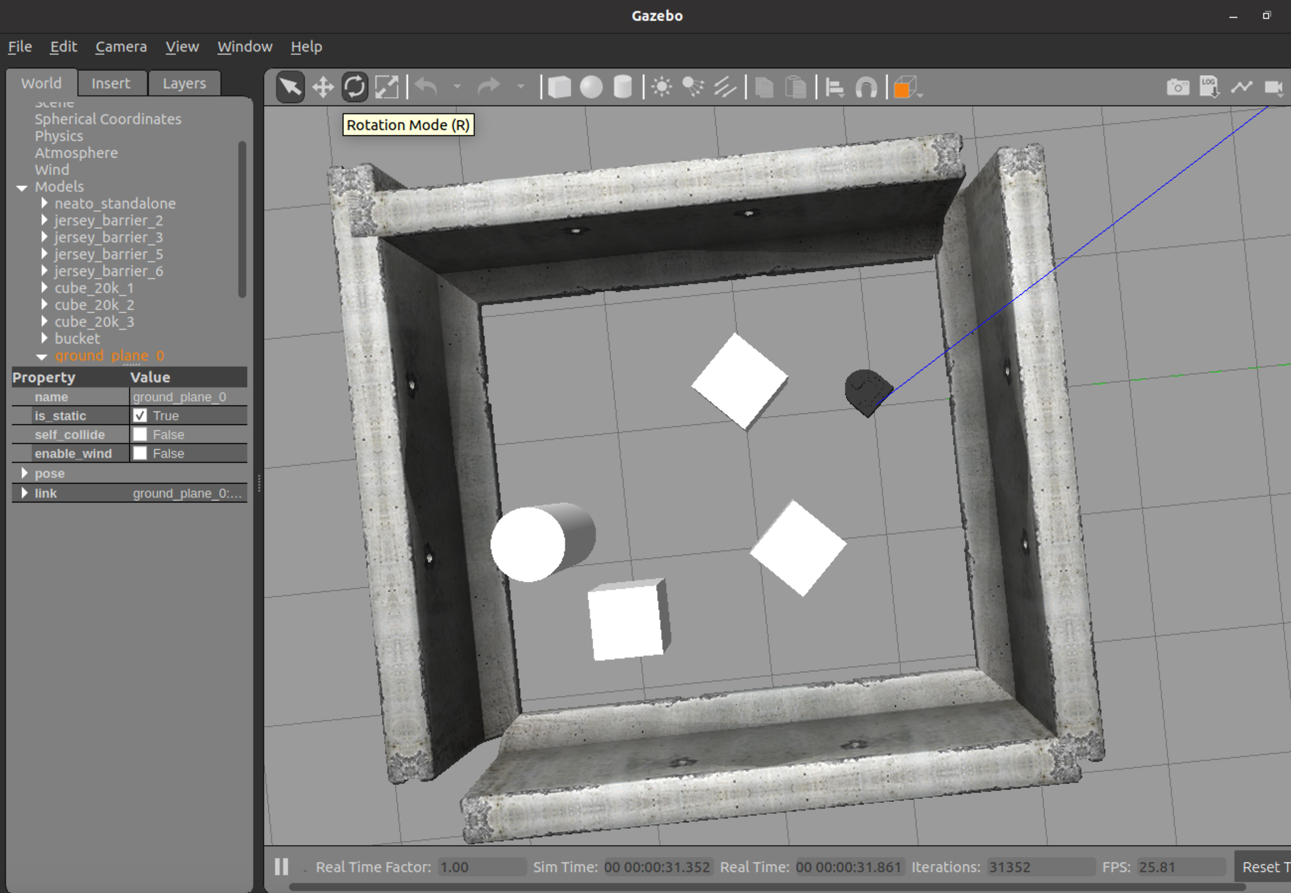
Populating the Simulated World
In order to populate the simulated world, you can use the “insert” menu in Gazebo. This will bring up a list of 3D models that can be inserted into Gazebo.
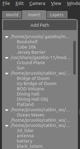
Click on one of these models and you should be able to drag it onto the Gazebo world.
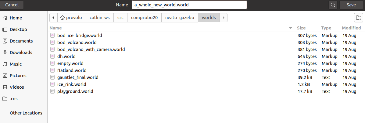
Saving the World
After you’ve built the world, you can save it using “file -> save world” from within Gazebo. You should save the world into the directory ~/catkin_ws/src/comprobo20/neato_gazebo/worlds as shown below.
Note: you must save your world to the directory specified above. Also, be sure that your world ends with the
.worldextension.
Loading the World
Assuming you performed the steps above to save the world, if you want to reload your world (e.g., you’ve shutdown Gazebo), you can load your world by running the following command (you should replace “a_whole_new_world” with whatever you named your world when you saved it. Also note that we omit the file extension .world in the command below).
$ roslaunch neato_gazebo neato_world_no_spawn.launch neato_world:=a_whole_new_world
Video Walkthrough
Some Cool Stuff About Simulators
While real robots are undoubtedly cool, there are some really awesome things you can do with as simulator.
Move Your Robot Around
Using the “move” tool in Gazebo, you can select your robot and move it around (so much easier than getting up and having to move your robot with your hands, right???). You can also set the location of your robot by using the rosservice gazebo/set_model_state (e.g., if you want to set the robot’s position in code). More detail on how to use the “move” tool is available on the Gazebo user guide.
Reading the Robot State
Oftentimes you may be trying to get your robot to execute a certain behavior. With a physical robot, you will usually assess success by observing its behavior visually. In a simulator, you can actually “cheat” and read the robot’s true state right from ROS. For example, if you were trying to get your robot to drive a square, you could compare the intended square to the actual square by reading the robot’s state. The robot’s state is available on the ROS topic gazebo/model_states.
Shutting Down the Simulator
Go to the terminal where you executed step 2 (launch Gazebo) and hit control-c.
Beta Features
This section includes things that folks might be interesting in utilizing but have some key limitations.
Support for Multiple Robots
Once you’ve done an update to your comprobo20 repository, you should be able to access a new launch file with support for multiple robots.
$ roslaunch neato_gazebo neato_world_2bots.launch neato_world:=flatland load_camera:=true
To pilot robot 1, run this command.
$ ROS_NAMESPACE=robot1 rosrun teleop_twist_keyboard teleop_twist_keyboard.py
To pilot robot 2, run this command.
$ ROS_NAMESPACE=robot2 rosrun teleop_twist_keyboard teleop_twist_keyboard.py
You should explore the topics by doing a rostopic list. You will see that the topics have now been placed into namespace.
Limitations
The biggest limitation is that the static transforms relating base_footprint to all of the parts of the robot are not properly handled. The only transforms that are properly namespaced are the ones that Gazebo publishes (namely base_footprint to odom). This is hard to support until